- Call us: 0129-2980757
- Email: sales@limitorqueindia.com
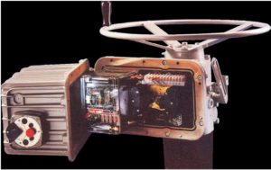
Hardware Control (UEC-3)
Hardware Control (The Universal Electronic Controller):
The UEC-3 is a micro-processor based control system for the complete range of Limitorque actuators. It offers a unique combination of features to provide complete flexibility in design of your control system while insuring maximum operating integrity.
“A comprehensive, electronic valve control package to protect equipment and process”.
Features
-
-
- Clockwise/ Counter Clockwise to’close’ rotation: Normally pre-set in factory but may be changed in the field by DIP switch slection.
- Remote Control from 24-125v AC or DC Supply : As standard, the users remote control supply may range from 24v to 125v AC or DC.
- Remote Control from Internal 24v DC Supply : The use of an internal 24V DC power supply and opto-isolated inputs reduces voltage drop problems, thus allowing control from remote volt-free contacts over long distances, and simplifyinbg the customers control system.
- Emergency Shutdown- ESD : A remote signal applied to the UEC-3 will override any existing signal, providing the actuators is in ‘remote’ and send the valve to its pre-selected shutdown position. DIP switch selectedable to give’CLOSE’, ‘OPEN’,’STAYPUT’ or ‘IGNORE’ mode. Motor thermostat may be bypassed during ESD –selected by DIP switch.
- Selectable Wire Control : Simple remote control connections and DIP switch selections provide a variety of control options with a minimum of wiring schematics.
-
2 WIRE CONTROL: Achieved by using a remote set of make / break contacts (e.g. on/off switch) and only two wires. The actuators will rotate in one direction when contact makes and in the other direction when it breaks. Directional mode may be selected by DIP switch.
3 Wire Control : Simple three wire connection and DIP switch settings allow the actuators to be configured for:
OPEN and CLOSE inching mode, with intermediate STOP when signal is
OPEN and CLOSE maintained mode, without intermediate STOP but retaining instantaneous reversal.
4 Wire Control : A four wire connection and appropriate DIP switch settings provide OPEN and CLOSE maintained control, plus intermediate STOP by push button, as well as the instantaneous reversal features.
- Monitor Relay : Monitors various functions of the actuator and provides a remote indication or alarm if a fault occurs and the units is no longer available for remote control.
 This relay is normally energized (1x SPDT contact) but will be de-energize if:
- Local / Off/ Remote selector switch is not in ‘remote’ position.
- One or more phase of the 3-phase supply are lost.
- Internal control supply is lost.
- Motor thermostat has tripped.
- Local ‘Stop’ button is depressed.
- Jammed valve detected.
- Contactor fails to energize.
- Electrical Interlock/ Sequence Control : The connection of remote contacts and setting of a DIP switch provides the means to either prevent electrical operation completely (Functional lockout) or until another operation has been completed (interlock or sequence control). This is effective in either or both the opening and closing directions and in both ‘Local’ or ‘Remove’ modes, but will be overridden by an ESD signal.
PROTECTION FEATURES
Autophase Correction : The UEC-3 monitors the rotation of the incoming 3-phase supply and automatically corrects the actuators controls to ensure that the motor always runs in the correct direction throughout the life of the unit.
The features is selectable on/off according to customers preference. As yellow LED illuminates when the phases are correctly connected. A red LED indicates that all three phases are present.
Lost Phase Protection : If one or more are lost the control circuit will be prevented from energizing the contractors. However, if an ESD signal is present, the loss of only one phase will be ignored and the actuator will attempt a shutdown in the direction selected, providing the actuators is already in motion prior ro rhe loss of that phase.
Anti– Hammer Protection : Torque switch hammer may occur when a ‘maintained’ control signal is present and the gearing in the actuators is non –locking, typically in high speed applications. The UEC-3 prevents this by moitoring both the ‘close’ and ‘open’ torque switches of the contractors in the same direction until a signal in the reverse direction has been applied.
Surge Suppression : Hiigh level surge suppression, to prevent damage to the control module or loss of functionality, has been included on all local and remote control input circuits. In compliance with EEC-EMC directive 89/336/EEC.
Jammed Valve Protection: The UEC-3 logic circuits provide automatic pretection against a jammed valve condition in either tbe open or close positions.
Auto Retry on Jammed Valve detection : If a jammed valve is detected, an automatic reverse/forward cycle is intiated to maximize the benefit of the lost motion hammerblow effect in the actuator drive and thus gives it another chance to free the valve.
Instantaneous Reversal : A time delay of 500mS, incorporated into the control logic of the reversing contractors, allow the actuators to be reversed without first pressing ‘stop’. This also reduces motor current surges and prolongs the life of the contractors.
OPTP-Isolated Inputs: All remote control inputs are ‘opto-isolated’ in order to protect the actuator logic circuits from high-voltage transients that might occur in the control cabling.
Motor Overloaf Protection: The motors have two thermostats embedded in the windings for protection against overheating. On detection of a thermostat trip, the UEC-3 will automatically de-energize the contactor.
SPECIAL FEATURES
2-Speed Operation In Both Directions: For the prevention of hydraulic shocks, a two speed timer with default pulse times is available in the closing and opening directions. It is DIP switch slectable and triggered by an intermediate limit switch which may be set anywhere in the valve travel.
Local Direction Indication : When the actuator is operating , the local pushbutton station LED’s will ‘Flash’ to indicate the direction od travel; One LED changing to ‘steady’ at the end of travel and the other LED turning off.
Comprehensive Diagnostic Port(Optional) : This port has access to the state of a number of circuit on the UECC-3 board and by plugging in a ‘hand held’diagnostic tool or PC the operator may quickly diagnose fault conditions, presence of inhibilt or ESD signals, etc.